
The projects involves the updating, enlargement and rationalization of the “Dock Road” with the aim to create an operational connection between the “port’s harbor” area and the area “outside the port’s harbor”.
The street will be equipped with viaducts, overpasses, culverts, retaining walls, rainwater and secondary services ditches (such as lightening service, electricity grid, drainage and water system). In this way, the “Dock Road” will also be used to position underground polyethylene pipes and cables necessary for the different services and everything will be obviously regulated by a specific agreement between the Port Authority and the several involved Companies, so to guarantee full control and constant maintenance of all secondary services.
This will truly benefit the port: the services available for logistic-commercial activities will use safe roads, with faster travel times and will have the possibility to eventually quickly continue on the external roads, therefore improving both efficiency and productivity of the companies which work in the port area and of the entire Integrated Logistic Platform.
The updating, enlargement and rationalization works for the ” Dock Road ” involves the creation of roads, lightening systems, electricity grid, drainage and water systems.
Operational characteristics of the Works
The main aims of the updating, enlargement and rationalization works of the Dock Road, are the following:
• upgrading of all roads to category D “Urban expressways” in compliance with D.M. 5 of November, 2001, Ministry of Infrastructure and Transport “Operational and geometrical regulations for the construction of roads”;
• creation of a link road with S.S. 106 “Jonica”, in compliance to category C1 “Extra urban Roads” of the D.M. 5 of November, 2001, Ministry of Infrastructure and Transport “Operational and geometrical regulations for the construction of roads”;
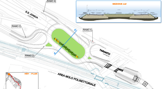
• connection between the Quay Street and the existing and future road system, with the creation of seven roundabout interchanges;
• updating of the public lightening system of all roads, including the connection road with the S.S. 106 “Jonica”;
• rationalization of the electricity grid thanks to the creation of a double MT and BT ridge;
• upgrading of the drinking water system;
• upgrading of the industrial and fire water system;
• creation of a communication ridge;
• upgrading of the existing drainage system, through the creation of new open flow and pressurized lines and through changes in the existing lines.
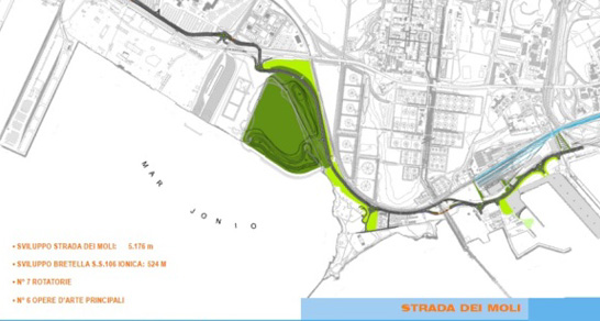
Work description
The roads’ projects involves two different routes:
– the new Dock Road, compliant to class D
– the new Dock Road, compliant to class D “Urban expressways” (with the only exception of the segment in between 1+200 and 1+800, which comply to class C1), for a total length of 5176.10 m;
– the connection road with S.S. 106 “Jonica”, compliant to class C1 “Secondary Extra urban Roads”, with a total length of 523.84 m.
The mileage point 0+000 can be found on the already existing Dock Road, near Wharf 4 and near the crossing point of two transport lines which head towards the port’s buildings of the wharf itself and of the 4th dock; the last segment is at mileage point5229.23 m and connects with the present road system so to create a two-lane road in both directions.
The layout of the roads has been enriched with transition curves having different ranges (clothoids) between the single elements of the route (straight roads and curves with constant radius), in compliance with the current regulations. In regards to height, the road path is strictly related to the fact that it is mostly created on the enlargement of an already existent route connected to numerous different public and private roads.
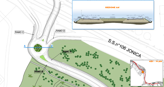
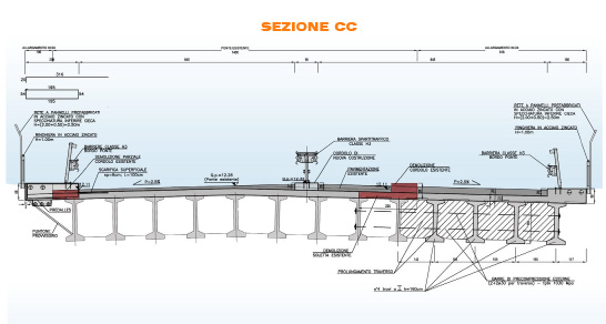
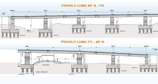
In fact, in order to overcome specific critical points, several bridges and viaduct will be created. In particular:
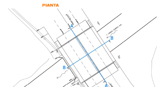
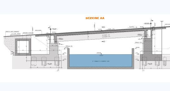
• Bridge B will serve the main rout of the ” Dock Road “, at the mileage point 3+776.79 and will allow the crossing of ILVA’s first drainage canal.
• Bridge C will serve the main rout of the ” Dock Road “, at the mileage point 4+689.48 and will allow the crossing of a paved road.
• Bridge D will serve the main rout of the ” Dock Road “, at the mileage point 4+876.34 and will allow the crossing of the railway overpass serving ILVA.
• Viaduct E will serve the connector between the ” Dock Road ” and the S.S. 106 Jonica, at mileage point 0+111.87 and will therefore allow the crossing of ILVA’s rail track and of the FS railway Taranto-Naples.
• Bridge F will serve the connector between the ” Dock Road ” and the S.S. 106 Jonica, at mileage point 0+446.80 and will therefore allow the crossing of ILVA’s second drainage canal.
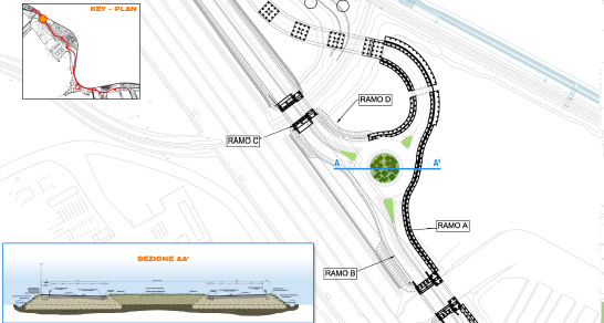
As said before, the main route of the road is classified, in accordance to the traffic laws as “Urban highway” classified as “D” and, starting from the central lane, will be therefore built as follows:
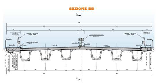
• a 1.80 m wide area where safety traffic islands barriers will be placed and with two adjacent passable quays 0.50 m wide;
• double way lane formed by 2+2 lanes, each 3.25 m wide, and lateral paved quays of 1,00 m width for a total width of 17.80 m.
• at the right external edge a bitumen passable quay wide 1.50 m will be placed;
• at the left external edge a bitumen passable quay wide 2.06 m will be placed;
• at the external right and left edge of the quay a small embankment 10 cm heigh and 0.50 m wide will be delimited by a bituminous curb will be also placed.
• at the external edge of the grassy scarp, with a 2/3 slope and final trench for the water collection.
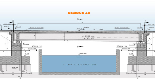
The velocity range is of 50-80 Km/h.
In the segment between the mileage points 1+100 and 1+450 the section of the road has a minor width equal to a half lane, due to preexisting structures (such as railways and buildings) and its structure will therefore be as follows:
• one way lane given by two lanes having a width of 3.25 m with lateral paved quays of 1.00 m and 0,50 m with a total width of 10.40 m, equal to half of the width of the “Urban highway road” class “D”;
• at the external right and left edge of the quay a small embankment 10 cm high and 0.50 m wide and delimited by a bituminous curb, will be placed;
• at the right external edge a bitumen passable quay wide 1.50 m will be placed;
Safety Guardrails
The safety guardrails dimensions have been determined in compliance with modern regulation; for urban highways classified in class D and C1, type III heavy traffic (most cautious situation) the following barriers are necessary:
• on raised edge: H2 class guardrail for raised edges;
• on bridges’ edges and on other structures: H3 class guardrails for structures;
• on bridges’ edges and on other structures: H2 class guardrails for structures;
• traffic dividers on raised edges: H2 class guardrail for raised edges.
During the design phase, we have dealt with several specific situations for which adequate possible solution have been found:
• barriers mounted on structures (bridges’ edges or on top of walls) near or above the railway line: H4 class barrier specific for structures;
• on raised edges: H4 class guardrail for raised edges;
• H3 class traffic dividers, specific for structures.
In areas where there is a high risk of mutual dazzling due to traffic and railway traffic conditions, safety barriers will be equipped with appropriate louvre elements.
Road Superstructure
The road’s superstructure is designed for the transport of first class loads and has the following structure, which can be applied to all the project’s traffic routs:
• 20 cm foundation layer, made of a stabilized granular mixture, together with a natural bounding substance;
• 25 cm of a mixed concrete layer;
• 15 cm base layer made by a bituminous mixture;
• 6 cm layer made of a specific binder;
• 4 cm for every usage layer;
Technological plants
Electrical grid plant and public lightening system
Electricity will be supplied thanks to four low tension separate points provided by the supplying Agency, with a tension of 230/400 V, 50 Hz. Downstream the four ENEL distribution points, four general switchboards will be placed; each one of them will have a power cabinet for all services (pumps, etc.) as well as a lightening power cabinet.
Electricity will be used for the following services:
• public lightening supply;
• power for waste water drainage pumps;
• power for sewage water drainage pumps;
• power for industrial water distribution pumps.
Lightening system
For the road and the traffic circle “F”, the lightening system will be provided by girders equipped with high pressure Na lights of 250 W, mounted on poles 10 m and 15 m high as well as spotlights equipped with high pressure Na lights of 250 W, mounted on poles 15 m; for traffic circles “A”, “B”, “C”, “D”, “E” and “G”, spotlights equipped with high pressure Na lights of 2×400 W, mounted on poles 25 m f.t. high.
For traffic circles “A” and “B”, two light towers will be placed for each one of them and will have five spotlights, while for traffic circles “C”, “D”, “E” and “G” a light tower will be placed for each one of them; rotatory “F” will be lightened using girders equipped with high pressure Na lights of 250 W mounted on poles 10 m f.t. high.
The position, number and type of the lights used will always fulfill the required lightening conditions in regards to the lightening category specific for the road.
For the management of the lightening system, power electronic controllers will be used (from now one, CEP) which will be placed near every energy distribution point, in order to guarantee the following advantages:
• power and light intensity reduction of all the system’s lights, according to a predetermined cycle decided by the user during the night period;
• reduced voltage plant start, in order to substantially limit the lights’ stress and starting voltage;
• stabilization (both increasing and lowering) of the downstream voltage of the different operational capacities, which may be by adjusted by the user;
• energy saving, since the voltage stabilization to predetermined values during normal operations and its reduction during the night will determine an energy saving ranging between 30% and 50%, depending on the light’s type and overall plant’s conditions;
• savings on maintenance costs, since the voltage stabilization carried out by CEP allows lights to last for a longer period, with an average lifetime of about 20000 hours
Telephone and telecommunications networks
Along the main route of the Dock Road and along the connection route with the S.S. 106 “Jonica” the following conduits will be created:
• a telephone line: casing tube having a diameter of 125 mm;
• a telecommunication line: casing tube having a diameter of 125 mm;
• also available: 2 casing tubes having a diameter of 125 mm.
Aqueducts for drinkable water
The project facilities will connect to the existing drinking water network (created by A.S.I. Group but not yet in function), which is formed by a steel conduit having a diameter of Ø 125 – PN 16.
The conduits carries on along the port and connected to the drinkable water network in two separate points: the first one is parallel to the 2nd ILVA drainage canal and the second one can be found near San Cataldo dock.
Near ILVA’s second drainage canal, the network divides in two segment: a first branch continues for 1400 m and serves the western sector of the port towards the sea outlet of the Tara river; the second branch, is 6500 m long and stretches on the eastern part of the port toward S. Cataldo Dock.
The projects involves the removal of part of the existing network and the creation of a new drinkable water network system in order to make fully available to all port services, all areas involved in the construction of the new Dock Road.
Industrial aqueduct network
The project involves the creation of two water networks which will supply industrial, commercial-logistic and fire prevention activities operating in the multi functional productive area during the creation of the Dock Road.
Both networks will originate in the collection tank, near the crossing between the S.S. Jonica and the railway route Naples-Taranto.
The collection tank is replenished by a adduction conduit which collects the water through a pumping plant on the Fiumetto river.
The first part of the network stretches along the S.S. Jonica and conveys the industrial flow rate to the final terminal near the ASI buildings.
The network, which is created with PEAD tubings, has a diameter of 250 mm and counts numerous connections for water distribution to the many industrial activities which will operate in the area and whose total number can currently only be estimated.
The second industrial network has a diameter of 200 mm and is formed by PEAD pipes running from the “collection tank”, near the Bellavista purifier, to the Logistic Platform following the Docks’ Road.
Waste water discharge system
The project involves the creation of a drainage system formed by a self-supporting reinforced concrete collector with a diameter raging from 50 to 120 cm, which will follow the roads’ routes on the sea front area of the Docks Road. The water of the streets convey in the collector thanks to storm drains positioned every 35 m; water collection is possible thanks to hard PVC tubings having a diameter of 315 mm and equipped with a siphon. The collected water will be conveyed to the treatment plants.
Furthermore, draining ditches positioned at the sides of the roads will also be guaranteed so to avoid water stagnations and water runoff in the surrounding areas. The water coming from the ditches will be mostly conveyed in the main drainage collector which is located downstream the first flush rainwater collection tank and will be purified directly in the continuous treatment plant together with the rest of the rain water. In paved drainage areas only, a first flush rainwater tank treatment is mandatory for all runoff water, which will therefore be collected in an upstream first flush rainwater collector.
The final drainage of the treated water will be at sea (tanks A, B, C, D, E), or in ILVA’s discharge canals (tanks F, G, H, I), in compliance with the General Development Plan of June, 2002 signed by Regione Puglia.
The removal of waste water and solid wastes produced by the treatment plants, must be carried out using tankers.
Sewage water discharge system
The sewage water discharge system will be integrated with the existing urban water collector which is formed by two DN600 tubes, in order to fulfill all the area’s necessities.
The system is formed by three main conduits which carry waste water and follow two procedures: partially by gravity and partially by pressure; two segments lead the waste water, collected in the areas of the multi functional dock and of wharf 4, to a junction point located at the South-East of the rotatory C, in which the third segment is also collected to the already existing purifier.
The project wants to realize a final sewage capacity of 17 L/s for the segment multi functional dock – junction point and for the segment wharf 4 – logistic platform, which is precautionary very similar to the total drinkable water capacity, that considers a possible drainage caused by the evacuation of the first flush rainwater tanks; the capacity gradually increases to 35 L/s due to the different inputs of the logistic platform.
The drainage capacity of the segment junction point – purifier, is given by the sum of the single inputs of the two segments and is equal to 52 L/s.
The first main segment follows the road near the sea heading East-North-West starting from wharf 4 to the junction point with the second segment, for a total length of 3125 m.
The second main segment follows the railway route Naples-Taranto, then the S.S. n. 106 and finally the planned road heading North-West – South-East starting from the multi functional dock (sea side) to the junction point with the first main segment, for an overall length of 2930 m.
The two segments converge in a pumping catch basin station, from which the third main segment leading to the purifying plant is formed. The pumping station of the junction point is mandatory in order to lift waste water and allow the gravity tubing to reach the end of the conduit without reaching excessive depths. The initial pressurized segment is given by a DN200 steel tubing, which originates from the pumping section and finishes in the discharging system, for a total length of 30 m. From this point, a DN400 gres gravity tubing 770 m long, will reach the purifier plant.
A lifting station will also be displayed in order to pump waste water to the height required to reach the purifying plant.
